How Parallel and Modular UPS Can Improve IT Network Resilience
When you install an uninterruptible power supply you are removing a single point of failure from your critical power path; the mains power supply itself. When there is a power outage your IT systems will continue to run on battery power. The runtime available should be long enough to ride through the power outage, start-up a local standby generator or initiate an orderly shutdown. But how resilient is your UPS and should you consider installing a parallel or modular UPS system?
Types of UPS System
Most uninterruptible power supplies installed worldwide are single phase monobloc UPS systems. This is not surprising given the number of applications which range from IT servers and networking devices to process automation, telecommunications, domestic and audio-visual (AV) systems.
The uninterruptible power supply installed will be one of the three types classified within BS EN IEC 62040-1:2019 as:
- Voltage and Frequency Independent (VFI-SS-111): referred to as an Online UPS (or ‘On-line’) and one using either double-conversion or triple conversion. This type of UPS has a constantly running inverter section which generates a digital sinewave output to power the connected loads. The power source for the inverter is the input rectifier/converter section when mains power (or generator power) is available or the battery set. The UPS therefore runs independently of the input power section in terms of voltage and/or frequency. An online UPS is also referred to as a static UPS in that its design is based on static electronics. Aside from the cooling fans and some relays, there are no moving parts. Rotary UPS are a different type of UPS system that rely on a motor to deliver uninterruptible power and are niche product design for large MVA applications. Online UPS systems may be transformer-based or transformerless in their design and provide premium-grade power protection from the widest range of power problems. As the output is digitally generated by the inverter section, the output voltage and frequency are tightly generated, and the output waveform is generally superior to the local mains supply making it ideal for sensitive IT servers, laboratory and scientific devices.
- Voltage Independent (VI): referred to as a Line Interactive UPS this type of UPS system uses a built-in automatic voltage regulator (AVR) or automatic voltage stabiliser (AVS) to provide protection from when the mains power supply is present, and charge the battery set. The inverter is energised but does not connect to the load until there is a power outage or the mains power supply fluctuates (voltage and frequency) outside of the operating range of the AVR/AVS. An EMI and surge filter provides additional protection from mains borne spikes, electrical noise and local lightning strikes. When the inverter section takes over supply to the load there is a short duration break in the electrical supply of typically 2-4ms which is easily covered by the capacitance of the switch mode power supplies built-into non-linear loads like IT servers and networking devices.
- Voltage and Frequency Dependent (VFD): referred to as a offline or standby UPS the output of this type of uninterruptible power supply tracks the input. The inverter is offline and switches in when the mains power supply fluctuates or fails complete. There may be some basic EMI and surge filtering built into the UPS. The transfer time to and from battery power can be longer than 2-4ms (relay based) and the battery runtime available at full load is typically of short duration i.e. 3-4 minutes.
For a typical server application online or line interactive UPS systems are the preferred choice. An offline or standby UPS should ideally only be used for desktop terminals and non-essential networking peripherals and devices.
As the number of applications for critical power increases within the server environment so must the size of the UPS system. There is therefore a natural progression towards online type UPS systems because line interactive type ranges tend to max out around 3kVA in size. In comparison, online UPS are available up to around 20kVA as a single-phase output system and up to 1000kVA or more for three phase UPS systems.
For more information on UPS design types and topologies see:
http://www.eaton.eu/ecm/groups/public/pub/eaton/@corp/documents/content/pct_1548681.pdf
Power Problems
Most applications are generally only concerned with power outages and tend to ignore the quality of their mains power supplies. A supporting factor to this trend is the quality of the switch mode power supplies (SMPS) used in modern electronic devices. These tend to be very reliable, operate over a wide input voltage range and can include their own EMI/surge filtering.
However, the more polluted the mains power supply is, the harder the SMPS electronics must work to maintain a stable output. This can result in increased ‘wear and tear’ which can limit the overall working life of the power supplies over time.
This can be demonstrated if we consider VA where V=Voltage and A=Amps. Assuming a Unity Power Factor output for the power supply, the Apparent Power (VA) will equal the Real Power (Watts) of the load. If the load requires a 230VA input, then 1A will be drawn from the mains power supply at 230Vac (single phase). If the input voltage reduces by 10% to 207Vac, the Amps drawn will increase by approximately 11% to 1.11A. The power supply must work harder to deliver the same output VA, and this can result increased heat within the power supply and a greater stress load placed onto individual circuits and components.
The range of typical power problems solved by the different UPS topologies are listed in the table below
| Power Problem | Online (VFI) | Line Interactive (VI) | Standby (VFD) |
|---|---|---|---|
| Sags | yes | AVR/AVS | Input tracking |
| Surges | yes | AVR/AVS | Input tracking |
| Brownouts | yes | AVR/AVS | Input tracking |
| Spikes/Transients | yes | filtered | filtered |
| Electrical Noise | yes | filtered | filtered |
| Power Outages | yes, no-break | yes, 2-4ms break | yes, >4ms |
| Frequency | yes | some | no |
| Harmonics | yes | no | no |
Extended Runtime Options
The amount of runtime required from a UPS battery is an important consideration. The runtime should be long enough to cover momentary power outages caused by local grid substation switching or overhead weather or local lighting strikes. The runtime should also be long enough to cover the power-up time of a standby power generating set, where installed or to commence and orderly system shutdown. The amount of time required for a complete system or site shutdown can vary from several minutes to hours. For some larger server rooms or datacentres, the possibly of a complete power shutdown is rarely considered.
How a UPS provides extended runtime varies by the type of UPS design deployed. All UPS can be run at load levels lower than their kVA or kW ratings. This reduces the load on their batteries and therefore increases the amount of runtime available. Online and some line interactive UPS systems can be installed with additional battery packs to increase their backup time.
Monobloc v Parallel UPS Resilience
A Parallel UPS system architecture can be deployed to increase the power capacity of the UPS system or increase its resilience from N to N+X where X is the additional number of UPS installed. The two types of configuration are referred to as parallel-capacity and parallel-redundancy.
UPS Bypass Modes
A single monobloc online UPS system has a high level of resilience. Compared to a line interactive or offline UPS, the online has a built-in automatic bypass. In an online UPS the bypass may be relay-based or static. Most online UPS incorporate static transfer switch technology. The relay-based approach is a lower cost alternative and may be used in UPS from 3kVA and below. The static UPS Bypass has a 0ms transfer time compared to 2-4ms for the relay based automatic bypass.
The bypass protects the UPS from overloads and high start-up load surges. Most switch mode power supplies have high initial switch on surges can overload the UPS. This start-up demand for power can be witnessed when a server is turned on. The internal cooling fans run up to full power initially and then reduce their speed and air volume flow based on the temperature and compute processing load. The running load of the server thereby reduces and places less load in turn on the UPS.
The automatic bypass transfers the load to the mains power supply if the power demand is greater than typically 120% or more of the UPS kVA/kW rating. As soon as the load demand reduces, it is reconnected to the output of the inverter. The UPS bypass also protects the UPS electronics and output stages from a short-circuit within the load in a similar manner.
Parallel UPS Systems
Parallel UPS systems provide an additional level of resilience compared to a monobloc UPS installation. Two or more UPS systems are connected in parallel and share the load between them. If one UPS is take out of circuit for maintenance, the other UPS set immediately supports the load(s). The same applies if one of the UPS develops an internal fault. This type of master/slave arrangement typically requires the UPS to be installed with parallel UPS operation cards and communications cables.
The UPS may be installed with their own battery sets or share a common battery installation. The UPS may share a local mains input supply or be supplied from separate substation supplies for additional resilience.
Parallel UPS configurations are typically adopted in more critical server environments and typically larger server rooms and datacentres. The architecture is like that of a modular UPS system.
Modular UPS Systems
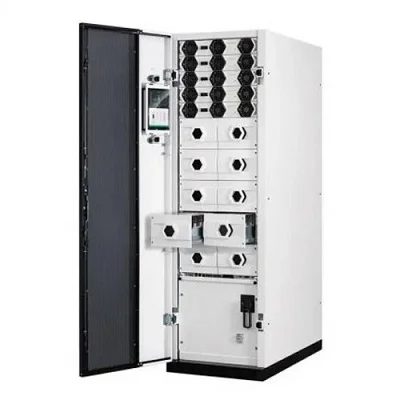
Modular UPS designs incorporate parallel-capacity and parallel-redundancy as standard. A modular UPS consists of a UPS frame size into which a set number of equally rated UPS modules can be installed. The installation (or de-installation) can typically be done ‘hot’ with the UPS in operation. This is only recommended where the module has been inspected and tested for any transit damage prior to installation.
In a typical server room or datacentre, the load may be 120kA. In this instance a 180kVA UPS frame could be used to house four 30kVA modules to give 120kVA or five to five 120kVA with N+1 redundancy or 150kVA capacity.
For a parallel UPS installation to be upgraded as easily as modular one, requires the complete electrical design to be installed on day one if downtime is to be avoided. Whilst this is also true for a modular system, the UPS frame size dictates the overall installation power requirements and provides the facility to easily add or reduce UPS capacity.
Where UPS modules are stored on site as part of a spares kit, these can also be connected into the UPS frame. In this instance the system architecture will cycle power module usage to reduce energy consumption and ensure only the required number of modules are ‘awake’ at any one time to support the load and resilience requirements.
Summary
There are key differences between UPS topologies. The strengths and weaknesses of these designs may not become apparent until the uninterruptible power supply is stressed by an emergency such as a complete power outage. Line Interactive UPS offer a high degree of power protection and are superior to offline/standby systems.
However, online UPS should always be the preferred choice for server rooms and datacentres. They offer a higher-grade of electrical power with the advantages of a built-in automatic bypass and therefore safe-failure-to mains should they be presented with an overload or fault condition. With an online system, further operational resilience can be added by installing a parallel UPS configuration. This can be achieved using two or more connected monobloc systems or by installing the more easily scalable modular UPS technology.


